Friday, December 14, 2012

Baby steps to MK-1 - General Coverage Receiver


Baby steps to MK-1 Presentation: Click Here (MK-1.ppt)

Hello Everyone,

We would like to introduce a new receiver to the family of receivers. First, we had the GR-40 which was a 40-Meter Rx. Then we have been busy with building a GR-20 Receiver, which is a 20 Meter Rx.

Then got us thinking why not build a general Coverage Rx. so that we can have multi-band support. Well these are the baby steps or stepping stones to building a multi-band Rx. Introducing the Mark-1 Receiver.

The MK-1 Rx. presently is covering a range from 1.5MHz to 7.5MHz. We have received a lot of DX on air and the gain is quite good.

More tech details and updates coming soon. Stay tuned.

Friday, December 7, 2012

GR 20 UPDATE


As per our Guru VU2VTM, OM Marcus (popularly known as Indian Marconi). We should always make more than two to three units to conform the repeat-ability of design.

We found 18.432 crystals is not easily available which were used as IF Filter. So we switched over to 10 MHz IF and anyway 10 MHz IF for 20 meters is standardized in world famous BiTx 20 meter TRx developed by our good friend OM Farhan VU2ESE. We made three GR 20 and here is the photo


The sample stations received: VU2AU, VU2OO, VU2RAK, ER4(Ukraine), VK6 ( Australia ), VU2KNN, VU2WWF etc.

Simple 20 meter drooping dipole is used. Here is the photo


Here is the component list for GR 20: Click Here (GR20) 

Wednesday, November 28, 2012

HAMFEST 2012 SPECIAL 20 METER HF RECEIVER - GR20

Greetings and Good news everyone!!!!!!!!!!!


On the occasion of HAMFEST 2012 we have made a 20 meter receiver, with 3 slight changes in the GR 40 receiver. The range of it is 200 KHz (14.059MHz-14.259MHz).

This year the All India HAMFEST 2012 is being held on the 15th December 2012 at Chennai,TN. This 20 Meter receiver was made for receiving foreign stations.

The schematic of 20 meter receiver is same as the GR 40 receiver except one trimmer capacitor. The capacitor C43 is replaced by Teflon coil. (For GR40 Rx. related documents please Click Here)

We have used 18.432MHz crystal (instead of 12MHz crystal which is used in GR 40). The I.F range is from 18.426MHz to 18.430MHz, for this the two resistor (R23 & R24) have changed to 22 Ω by which the range of I.F is 3KHz. To change the BFO frequency we have used a Teflon coil in place of Trimmer C43. The coil dimensions are 7 mm long *10 mm diameter with 13 turn, the gauge of a wire is 22 SWG. The two legs have to be mounted such that one is to be grounded and another is to live.

In RF the inductors L1 and L2 are changed to 15 turn on 13mm long *10 mm diameter coil , the gauge of a wire is 26 SWG. The capacitors C5,C7,C11.C6 are changed to 47pf and C12,C13 to 180pf. The range of RF is from 14.059MHz to 14.259MHz, (which is obtained as RF=IF-VFO)

The receiver is working beautifully. It is tested on air and received the very clear and strong signals from VU2AU,VU2OO (Madhya Pradesh), VU3RAZ (Nagpur) and VU2KNN Rajan (HYD).


Monday, November 19, 2012

35W Solar Charge Controller - Prototype

Hello Everyone,

We finally have our prototype build thanks to one of our RnD Engineers. This is project was started to help students all over the world to face the power failure issue. Read our previous post for the detailed version. Click Here.

For testing the prototype we are using a power supply as the solar panel input for now for testing purpose. Once the Solar Panels are fixed, we shall update the full working system.

Suggestions and feed back are most welcomed.


Friday, November 16, 2012

NorCal20 - Cute CW box

Hello Everyone,


We have successfully tested the receiver of the NorCal 20 and have sent it for field test or rather get it live on the band to hear some stations.

We are waiting for the results.........Stay Tuned...........(To be Continued).

Tuesday, November 13, 2012

35W Solar Charge Controller

Hello Everyone!!!!!!!!!!

This project is focused and contributed to all the students all over the world who face serious power failure issues. Hence, we have great news for all the students around the world facing great power failures. 

RnD Labs have designed a 35W Solar Charge Controller to be integrated with online inverters of 300VA capacity running with single 12V Battery and one 35W Standard Solar Panel. This 300VA UPS will light up one table lamp and one table fan of total capacity 65W for 4 hours. Generally, we have 2 hours power(E.B.) minimum in the night and that should allow children/students to get up early morning 4am and study well. 

The Charge specifications are 12V, 3A capacity, enough to charge a battery for UPS Systems. Thus, giving a suitable time of power backup during failures.

Few technical details and as generous as always we have provided the Schematic and the Program. Please feel free to copy, copy-left ©

(Note: The copyleft symbol may not be supported in Internet Explorer)

Functionally this Charge Controller does:

1. Generally keep the battery on full voltage condition. 
2. Prevent the battery from over-charging. 
3. Prevent the battery from supplying power to solar panels during nights.   

Electrical Specifications:
Battery Voltage: 12V DC
Charge Voltage: 13.7 V DC
Charge current: 3A 


The prototype is under construction and once the construction is fully completed, we shall upload the tested working development board and pictures.
 

 Downloads:

Schematic: Click Here(PDF)
Main Program: Click Here(main.c)

Complete Program:

#include<htc.h>
#define _XTAL_FREQ 8000000

__CONFIG(FOSC_INTOSCIO & WDTE_OFF & PWRTE_OFF & MCLRE_ON & CP_OFF & CPD_OFF & BOREN_OFF & IESO_OFF & FCMEN_OFF );


#define Battery PORTAbits.RA2
#define Switch PORTCbits.RC2
#define Voltage_level 0x00            //Set the threshold value here

unsigned int adc_value,adc_value1,adc_value2=0;


void main()
{
OSCCON=0b01110101;            //Setting internal oscillator in 8MHz
CMCON0=0x00;                //Disable the comparators

ANSEL=0b00000100;            //Set RA2 as Analog
TRISA=0b00000100;            //Set RA2 as input
TRISC=0b00000000;            //Set port C as output

ADCON1=0b00100000;            //select analog clock as FOSC/32
ADCON0=0b10001000;            //Select analog input channel as RA2

while(1)
    {
    ADON=1;                    //Start ADC
    __delay_us(100);        //Wait for acquisition time
    GO_nDONE=1;                //Start conversion
    while(GO_nDONE);        //wait until conversion to be done
    ADON=0;                    //Stop ADC

    adc_value1=ADRESL;                      //Read Lower 8bit registers
    adc_value2=(ADRESH<<8);                 //Read the higher 2 bits and shift it in to 8th and 9th position using shift function
    adc_value=adc_value2|adc_value1;        //OR both after reading to make a 10bit value
       
    if(adc_value>=Voltage_level)            //Compare with the voltage level and switch On/OFF the charging
    Switch=1;
    else
    Switch=0;


    }


}

Friday, November 9, 2012

Intelligent Load Management and Alarm monitoring System for 10KW Solar Charge Controller

Greetings,

We would like to reveal the secret behind Intelligent Load management and Alarm monitoring Algorithm for 10 KW Solar charge controller.
First of all thanks to the beautiful compiler HIGH TECH C. This  algorithm is developed with the help of HIGH TECH C PRO for mid range MCU  evaluation version.

The major purpose of this algorithm to manage the load in 15 Amperes per hour.The rated discharge given by customer is 360AH per day. So for 5 days its around 1800 Amperes . We need to limit the discharge in this range so it can work continuously for 5 sunless days.

According to the requirements of our customer we need to develop an algorithm in order to sense the battery voltage  and switch the load ON/OFF  with the level of voltage from battery.There are so many visible alarms that are present in our system, so its mandatory to produce a warning audible sound for each alarm. This algorithm is capable for doing that also.


Main goals of this algorithm

Part 1.Sense the battery voltage and manage the Load
Part 2.Sense the visible alarms from the system and activate audible alarm and Switch off the audible alarm if reset button is pressed. (Here the audible alarm will be turned off, irrespective of the status of visible alarm)

Check points for Part 1.
1.If the battery voltage is above -51.6 Volts switch On the load.
2.If the battery voltage is below -44.4 Volts switch Off the Load

This is very simple, but need to form a hysteresis loop because when ever it is below -48 Volts it need to shut down the load and need to connect it only after -55.2 Volts. In the same way it can connect load up to a voltage of  -48 Volts.
Here we are utilizing the 10bit Analog to digital converter module of PIC16F88 (18 pins) for doing this task.

Check points for Part 2.
1.If the visible alarm is ON, the sensing digital input of MCU will be high. If the alarm is OFF ,then it will be LOW .So according to this sensing I/O pin's status switch ON and OFF alarm. But the tricky thing over here is if user resets the Alarm , audio will be OFF, but still the sensing I/O pin status will be same as the visible alarm status. So here literally we need to sense a transition from LOW state to HIGH state and switch on the alarm.

The algorithm is having 3 functions mainly,
1.For sensing the battery voltage and switching the load- ADC_Function
2.For sensing the LOW to HIGH transition and switch on Audible Alarm-Alarm_Function
3.For Sensing the Reset button press and switch off Audible Alarm-Reset_Function


PROGRAM:-


/*********************************************************************************
*        Program for 10KW charge controller                                                         
*        Intelligent Load Management and Alarm monitoring System                                                                                           *
*        Author: Ravi M.D.                                                                                                                                                        *
*        R&D Engineer, Miconova Impex PVT LTD                                                                                                        *
*        Date 10/30/2012                                                                                                                                                                                         *
********************************************************************************/


#include <htc.h>
#define _XTAL_FREQ 8000000                   //Set frequency as 8MHz

#define Alarm PORTAbits.RA7                 //Assign I/O Pins
#define Signal PORTAbits.RA6
#define Reset PORTAbits.RA0 
#define Load PORTBbits.RB4
#define Lower_Voltage 0x015E               //Set the voltage ranges here. No need to change in program
#define Upper_Voltage 0x0101

//Internal Clock used at 8MHz

__CONFIG (FOSC_INTOSCIO & WDTE_OFF & PWRTE_OFF & MCLRE_ON & BOREN_OFF & LVP_OFF & CPD_OFF
                        & WRT_OFF & DEBUG_OFF &CCPMX_RB0 & CP_OFF);

__CONFIG (FCMEN_OFF & IESO_OFF);

unsigned int adc_value,adc_value1;adc_value2=0;      //Reading variables for adc higher and lower    registers
int i=0;                                                       //Variable for switch function
bit out_bit=0;                                                 //Bit used for Load ON and off


void Alarm_Function(void);                //function to rise alarm
void Reset_Function(void);                //function to reset alarm


void main(void)
{
 OSCCON=0b01110110;                                //Oscillator Setting  for 8MHz
 TRISA=0b01000011;                                //PORTA configuration
 ANSEL=0b00000010;                                //Only RA1 as analog input
 TRISB=0b00000000;                                //All pins are digital out


 ADCON1=0b10000000;                                //References are VDD and Vss and right justified
 ADCON0=0b10001000;                                //A/D clock as Fosc/2 and channel 1

 while(1)                                          //Check infinitely
 {
 switch (i)
            {

/*ADC_Reading for battery management*/

                case 0:                                                
                ADON=1;                                 //Start ADC Module
                __delay_us(100);                        //wait for acquisition time
                GO_nDONE=1;                             //Start conversion
                while(GO_nDONE);                        //Wait for conversion to be done
                ADON=0;                                 //Turn OFF ADC
        
                /*Reading the 10 bit ADC values*/
                
                adc_value1=ADRESL;                      //Read Lower 8bit registers
                adc_value2=(ADRESH<<8);                 //Read the higher 2 bits and shift it in to 8th and 9th position using shift function
                adc_value=adc_value2|adc_value1;        //OR both after reading to make a 10bit value
        
        
        /*Switch ON and OFF load according to the condition*/
        
                if(adc_value>=Lower_Voltage)            //Compare with lower voltage range
                out_bit=0;                              //If less than the (here negative voltage so thats why used greater than or equal) lover voltage level, switch OFF load
                
                if(adc_value<=Upper_Voltage)            //If greater than the (here negative voltage so that's why used less than or equal) upper voltage level, switch ON load
                out_bit=1; 
                
        Load=out_bit;                                    //Assign the decision to load.(Important, Its done here to resolve a fluctuation problem)
        break;


        /*Checking alarm conditions*/        
                
                case 1:
                ADON=0;                                  //taking precaution by switching OFF ADC and setting the same value as above to the load
                Load=out_bit;
                Alarm_Function();                        //check for alarm condition
                Reset_Function();                        //Check for reset condition
                
        break;
                
                }
 i++;                //Iteration variable to exit the switch case and repeat the process
        if(i>1)
        {
        i=0;
        }
 }
        

}


Sub Routines:-

1.Alarm_Function:-


#include <htc.h>

#define Alarm PORTAbits.RA7
#define Signal PORTAbits.RA6
#define Reset PORTAbits.RA0 

bit flag=0;                        //flag for identifying the signal transition from 0 to 1

void Alarm_Function(void)
{

if(!Signal)
        {
        flag=1;
        Alarm=0;
        }
        if(flag&&Signal)                //Check whether there is a signal change from 0 to 1 is happening
        {
        
                Alarm=1;
                flag=0;
        }
        
}     


2.Reset_Function:-


#include <htc.h>

#define Alarm PORTAbits.RA7
#define Signal PORTAbits.RA6
#define Reset PORTAbits.RA0 

void Reset_Function(void)
{

        if(!Reset)
        
        Alarm=0;

}


Friday, November 2, 2012

NorCal20 - Updates

Greetings,


Great news. We tested the NorCal20 receiver side today. The receiver IF was tested by feeding a RF Gen signal for the RCT of 8.998Mhz. A blasting crisp noise was heard.....PASSED.

The audio amplifier was also tested during the process.....PASSED

More updates awaiting.

10KW Solar Charge Controller - Tested and Parceled

Hello Everyone,


The above picture is the final stage of the 10KW Solar Charge Controller. This product has been sent to the customer for testing and reviews. We have already tested the unit in a Bangalore test facility (Our previous post has the history).

Saturday, October 27, 2012

10KW Solar Charge Controller

Season Greeting Everyone,

Front Panel


Finally, the 10KW Solar Charge Controller was tested in a facility in Bangalore. Honestly, the facility in Bangalore did not have a proper 10KW system. So, we were restricted to only test upto 8KW.

Our Solar Charge Controller is designed with the mentioned specifications: -48V, 200A (yes, it is negative 48 Volts). The facility in Bangalore had a capacity to only run the system at 160A and was refusing to go beyond the ampere rate.

Few observations of the system during testing: the temperature rise was quite moderate for the power components used. The max. temperature recorded was about 60 degree Celsius. The temperature was recorders using Thermal Sensor with Fluke system which was connected to a PC through Serial Port.The Hyrda Software designed for Fluke Company was recording the temperature of all the power components in the Charge Controller for interval of 600 seconds.

Second key observation is the the wires that were used to the interconnect the whole Charge Controller. The theoretical knowledge generally around is that for 1 sq. mm of copper wire, we can use it for 10A rating. Well, that was quite false and proven by the test. We approximated the rating to 3A-4A per sq. mm of copper wire.

Well, we are already on the move to construct the next system with better enhanced heat-sinks to dissipate the heat faster and better, improved looks and far better design.

We are welcome to accept commercial requests as this Charge Controller is designed for Telecomm products and may not be suitable to all. Please feel free and send us requests or suggestions.


Saturday, October 13, 2012

NorCal 20 - 99.90% Construction

Hello Everyone,


We have finished 99.90% construction of the NorCal 20. The remaining 0.10% is the testing of the NorCal 20 on air. The previous post had only the receiver unit assembled, now the transmitter unit is also constructed.

Soon, the test results will be posted. Stay tuned in......

Friday, October 12, 2012

Digital Ammeter using IC7107

Hello Everyone,

We have another great success to share with our readers and well wishers.

Digital Voltmeter using IC7107 was posted quite recently and we had made beautiful double sided PCB for the DVM's. Well we have managed to use the same PCB to display the Current too.

The formula is quite simple and it is not a new discovery as such. Refer to the diagram below:

We know that to measure voltage we connect the voltmeter in parallel and to measure current in a circuit we connect it in series. Now we all are aware of the famous Ohm's Law:

V = I * R

If we select the Shunt value or the R value to be 1, then the formula above reduces to:

V = I

So, keeping the points above in mind, I can effectively say that if R = 1 ohm or in orders of 1 milliohm, then when I measure the voltage it is as good as getting the current reading as V = I.

Hence the selection of the shunt value is quite crucial and the there is a a small change in the circuit. Refer the circuit below: Click Here


How did we test our Digital Ammeter?

We have selected a shunt of the specification 200A, 200 mV. So, that gets us R = 1 Milli-ohm.

Hence, by measuring the voltage across the shunt will be equivalent to calculating the current. That is, measuring 1 mV is like measuring 1A and 200mV is like measuring 200A.

Please note that the only difference in the PCB would to replace the 1Mohm used in the DVM by a 10K and the 1K resistance is removed.

In summary, we are just measuring the voltage and displaying it as current. Old school trick.


Thursday, October 11, 2012

NorCal 20 - Under Construction


Hello Everyone,

We always had and will have a soft corner for HAM Radio Community and are willing to extend our helping hands to reach out.

A very Senior HAM operator and a well wisher approached us to help him build the famous NorCal 20 Transceiver kit.

What is NorCal 20?
It is a QRP CW Transceiver for 20 meters. (More details in depth coming soon!!)

In less than 2 weeks, our RnD Engineer has already finished the receiver part of the NorCal 20 and we are presently testing the receiver. Once we receive a few stations in the NorCal 20 Receiver, we shall progress to the Transmitter. Receiving a few stations on the receiver will give us confidence that the construction is fine to proceed to the transmitter.

Soon we shall have more updated of the famous NorCal transceiver.

Keep checking!!!!

Tuesday, October 9, 2012

Final Digital Voltmeter using IC7107

Hello Everyone,

It has been quite sometime since our last visit to the blog. Well the excuse would still be the same, we are busy with Secret X Project. Well the commercial project we are attacking at the moment requires the use of DVM to display voltages and also polarity.

PIC Microcontroller would be a good option but then to simply display voltage a microcontroller will be an overkill or under-utilized.

Hence, we choose a popular IC used in multimeters for a very long time. IC7107 is manufactured by Intersil and 3-1/2 Digit, LED Display, A/D Converter. It is purely dedicated to just drive 7-Segment LED Common Anode Display units and has built-in A/D Converter.

The beauty of the DVM is that it displays +/- voltages. The circuit is quite straight forward with the datasheet having the circuit and various modes of configuration. After building the DVM, the Reference Voltage has to be set to Calibrate the DVM to display the right voltage. This Calibration is achieved by setting the 10K pot. to either 100mV or 1V depending on the number of decimal places required. Also the DVM works on 5V only. The IC7660 is a voltage converter to generate -5V as negative reference in order to show us negative readings.

IC7107 Datasheet: Click Here
DVM Schematic: Click Here

Our previous post had the GPB (General Purpose Board) model. We got the PCB made to have the professional edge. Have a look at the pictures. Circuit is provided below.

Front and Back of the DVM (Quiz: which is the Front and Back ?)
DVM displaying Positive Voltage

DVM displaying Negative Voltage
 We would like to provide the schematic though the datasheet has provided which has a lot of ambiguity. 


Monday, September 17, 2012

Digital Volt Meter using ICL7107

                                                  
Hello Everyone!!!!!

Previously we made Digital Voltmeter using PIC16F688,but now we made the same digital voltmeter using  ICL7107.We have used ICL7107 because it displays both positive and negative voltages and the second reason to use this IC was that it is cheaper than the PIC16F688 which was used earlier and no programing is required for ICL7107.

The datasheet of ICL7107 can be downloaded by:clicking here


We wasted almost 2 week on making Digital voltmeter by taking help of  below mentioned site and then we modified the circuit and made it work.Digital Voltmeter we made is used for measuring the output voltage of your DC power supply and include 3.5-digit LED display with negative voltage indicator.This circuit should be supplied with a 5v voltage supply and consumes only around 25mA. 

You can find the link by:clicking here
Here is the modified circuit and the JPEG download of the circuit:click here


Have a look at some working snapshot of Digital Voltmeter using ICL7107.


Tuesday, August 21, 2012

IGBT Testing in RnD Labs

Greetings,

A few days back we had posted in our blog some pics and explanation on some High-Power devices. But never had we mentioned that we have put them in test right!!!!!

Today we have tested a High-Power IGBT in the order of 600V, 374A but we shall be utilizing only 60V,200A. Why are we using an IGBT? well, for a secret "X" project for BSNL. The tested voltage is -30V (minus thirty volts). A small picture proof and also a circuit diagram for reference is provided below.

IGBT used: GA200SA60SP (Datasheet: Click Here)


Thursday, August 16, 2012

N-Channel MOSFET Testing with Analog Multimeter


The right way of testing an N-Channel MOSFET transistor is to use an Analog Multimeter. First, find out the Gate, Drain and Source from semiconductor replacement book or search its datasheet from search engine.

Once you have the cross reference or diagram for each pin of the MOSFET and your Analogue Multimeter, follow the below instructions:-

  1. Set to times 10K ohm range to check it.
  2.  Put the Black Probe to the Drain pin.
  3.   Touch the Gate pin with the Red Probe to discharge any internal capacitance in the MOSFET.
  4. Now move the Red Probe to Source pin while the Black Probe still touching the Drain pin.
  5. Use your finger to touch the Gate and Drain pin together. You will notice the Analogue Multimeter pointer will move forward of the meter's scale.


 How to cross-check?

Lifting the Red Probe from the Source pin and putting it back again to the Source pin and the pointer will still remain at the middle of the meter's scale. To discharge it you have to lift the Red Probe and touch just one time on the Gate pin. This will eventually discharge the internal capacitance again.
At this time, use the Red Probe to touch on the Source pin again, the pointer would not kick at all because you have already discharge it by touching the gate pin. 

These are the good MOSFET characteristic. 

If you notice that all the result that you measured kicked towards zero ohms and will not discharge, then the FET is considered shorted and need replacement. Testing the P channel MOSFET is just the same way as when you check N channel MOSFET. What you do is to switch the probe polarity when checking the P channel. Some Analog Multimeter have the times 100k Ohm range, this type of meter can’t really test FET due to the absent of 9 Volt battery inside the Multimeter. This type of meter will not have enough power to trigger the MOSFET. Make sure you use a meter that have the times 10k ohm range selector.

Thursday, August 9, 2012

Mega-High-Power Components

Greetings!!!!!!!!!!

We are burning our hands in Power Systems and with outputs in the range of 1K-Watt to 10K-Watt.

In order to work in such high powers, we have work with high Amperes and high Voltages usually in the order of hundred's simply because of the Power Law: P = VI

The main reason for this post to just share information with our readers, followers and well-wishers of the high power components used in the industry. The package of the high power components are called ISOTOP or SOT-227 package. The big black chunk of seen in the below picture is the ISOTOP of the related component. The datasheets are provided below for further information.

Below are a few pictures of the components we are using in our Power Systems.

MOSFET and IGBT - IRF5210, GA200SA60SP and IRF640

Diodes - IN4007, 1N5822 and STTH12003TV
Datasheets:

IRF5219: Click Here
IRF640: Click Here
GA200SA60SP: Click Here

1N4007: Click Here
1N5822: Click Here
STTH12003TV: Click Here
 

Thursday, August 2, 2012

Dual Voltage Display (0-20v)


 Hello Everyone,

More developement on Digital Voltmeter Using PIC16F688.

 In previous voltmeter we used to measure only one voltage value.But the voltmeter is modified to diplay two voltages simutaneously.

In modified voltmeter we have assigned pin12 (RA1) as one input and pin11(RA2) as the other input to PIC16F688. The voltage to be measured is fed to one of the 8 analog channels. The reference voltage for AD conversion is chosen to be the supply voltage Vdd (+5 V).A resistor divider network is used at the input end of pin12 and pin11 to map the range of input voltage to the ADC input voltage range (0-5 V).

 Modified Program:Click here

Output

 The  DVM is tested for various input voltages ranging from 0-22 V and some snapshots of the tested DVM are given below.


Wednesday, July 25, 2012

48 Volts 60 Ampere Solar Charge Controller

Hello Everyone.......

An update to our work in Rnd Labs. A solar charge regulator or controller (as you wish), which is based on the PWM Mode built using a PIC Microcontroller. We shall see block by block explanation of the whole unit.


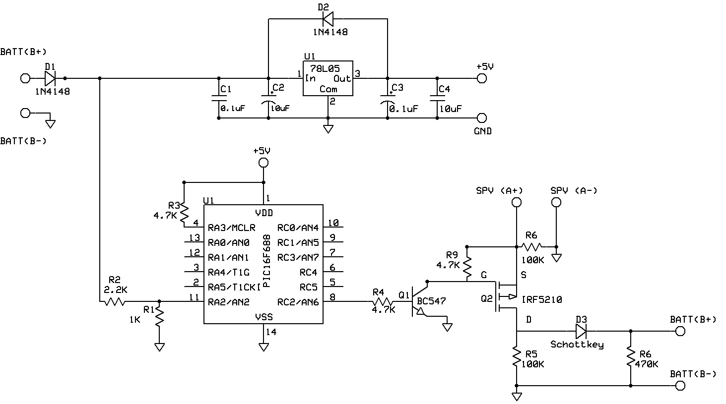
Here is the schematic for the whole unit:


Here is a file to download in case it is not viewable on your screen: Click Here

Let me first attack the Micro-controller based ADC and PWM units as this is the main unit which does one half of the work.

For the ADC, we are exclusively using the PIC 16F88 as it has a built in ADC converter and also its quite small in size with 18 pins. We have already covered the ADC in this post here: Follow Here

Now coming to the PWM, the PIC16F88 does have a built in PWM, but here we have to re-alter the PWM in a different way which has been explained below.


The following is some simple algorithm with pseudo-code at some places to help better understand the flow:-
; Simple 2-Stage algorithm

; Determine the hex values for 53Volts and 60 Volts
; R1 equ   53h
; R2 equ    60h

; Please note these R1, R2 values are due to scaling
; In the present case scaling is 100:5
; Determine the present Battery Voltage Say R3

10; If R3 < R1 Call Dump routine
20; If R3 >R1; If 'False go to 10”; Call PWM Routine

; Dump Routine;
; BSF Rb4; (Rb4 is the Driving output and it is set High;
; Call Delay 2sec;
; BCF Rb4; (Rb4 is set low);
; Return; Go to 10 meaning continue to check whether;
; The Battery voltage has crossed the Desired R1 Value;

; PWM Routine;
; R2-R3=R temp;
; BSF Rb4;
; DECFSZ Rtemp;
; Loop;
; BCF Rb4
; DECFSZ RTemp2; Rtemp2 + Rtemp=C (Constant);
; Loop;
; Return;
; Go to 20 
; End;

1) Effectively we determine what should be the HEX values for 53Volts (R1) and 60Volts (R2).

2) We are continuously monitoring the Battery voltage (R3)

3) If Battery is below 53 Volts we go to dump routine and make the Controller output High for 2 Seconds. Then we Make the output Low and verify the status of battery Voltage.

4) We continue with Dump stage till Battery crosses 53Volts.

5) Then we verify whether it has crossed the set value of 53 Volts and jump to PWM Routine.

6) PWM Routine: Here we check the difference between higher cutoff voltage and present voltage. The difference is ON time of PWM Off time is the inverse Meaning ON+OFF shall be same.  (On+Off gives us PRF)

7) Continuous loop from step 2

Technical Details of the Solar Charge Controller:
 
The energy coming from Solar Panel is used to charge battery using this Charge Controller.Two-Stage Controller is implemented in 16F88 Microcontroller. Charging is done in two stages: boost charge upto 53 volts and PWM method beyond 53 volts. The algorithm is provided above.

The cabinet  is all aluminum. Three sides are covered by heat sink. Chassis DOES NOT consists of any heat dissipating components.

Two diodes are used to provide reverse polarity protection for solar panel as well as battery. Each diode rating is 180 Amperes (ie, 90A*2), whereas we are pumping only 60 Amperes. The maximum dissipation is 60 Amps* diode drop which is below 150 Watts. We have provided heat sink for 200 Watt capacity each.

The MOSFET switches have resistance loss Rds=0.065 ohms.
Each MOSFET, theoretically can output 40 Amperes, whereas, we are loading only 12 Amperes. So the voltage drop is 0.78 Volts and dissipation is 9.5 Watts. Total MOSFET dissipation is 5*9.5=50 Watts as we are loading 5 MOSFET’s to share the load current. The heat sink is 500mmx100mm heat sink profile.

The selected heat sink is rated 500 Watt dissipation at Ta=25 degree centigrade.

 Finally, our unit under testing.

The complete code for the Micro-controller can be downloaded from here: 
ADC-PWM: Click Here(ASM)
ADC-PWM: Click Here(HEX)