
Welcome back fellow bloggers, readers, well-wishers and mates.
If you have observed, we at RnD have not been posting your findings and projects from the month of April. Why? Well, the RnD team is quite busy researching, destroying and putting our hands into power modules. For the past few days, members of RnD are testing and getting the shock of their life with SMPS amd MOSFET's jumping around the Lab. With a lot of shocking experience in the SMPS technology the team had a lot of charge and enthusiasm to step over to the Charge Controller.
Coming to the Charge Controller, we wanted to build one which can charge a 12V, 100Ah Battery. Why did we want to build a Solar Charge Controller? Sorry but its a Company Secret. Lets just say we want fellow people to utilize the Solar energy that we have in everyone's daily life. It's free and there is not charge or Tax to use Solar Energy (Fingers crossed that no rule will come hopefully).
An adaptation of the The Micro M+ from The ARRL Handbook 2002 edition was built in the RnD Labs. Again, reminder that it is an adaptation and not a copy as the article has a lot of components that is mentioned is American components which may or may not be available in the Bangalore, Indian electronics component market. If anyone would like to read the article, refer any of the ARRL handbooks from 2002 to 2009.
The Charge Controller was first test last week with a power supply (which is not correct/method - but we did not have a Solar Panel). The charging of the battery was fine when the battery was discharged and the charge controller would stop charging when the battery was fully charged. Now for the real test, we requested TATA BP SOLAR to help us out and test the prototype. Their facility has a lot of equipment and were very kind enough to help us. A 80W solar array panel was provided and our charge controller worked beautifully. The battery was a tubular 40Ah battery and the charge controller was cool and was doing the job.
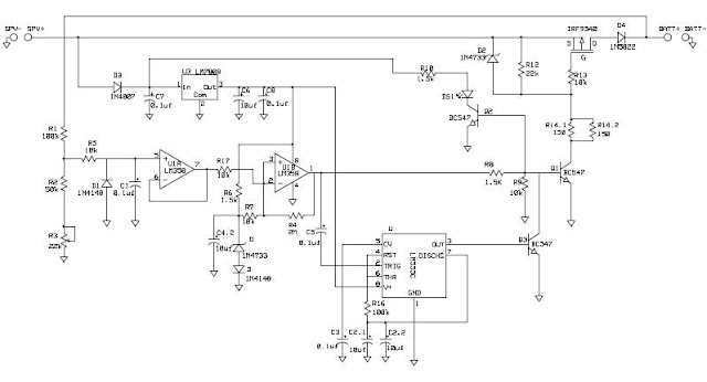
Some of the features of the charge controller:

Here is the schematic of the Charge Controller : Click Here
We shall keep updating the post for more info and finding. Suggestions are most welcome and doubts will be cleared if any.
If you have observed, we at RnD have not been posting your findings and projects from the month of April. Why? Well, the RnD team is quite busy researching, destroying and putting our hands into power modules. For the past few days, members of RnD are testing and getting the shock of their life with SMPS amd MOSFET's jumping around the Lab. With a lot of shocking experience in the SMPS technology the team had a lot of charge and enthusiasm to step over to the Charge Controller.
Coming to the Charge Controller, we wanted to build one which can charge a 12V, 100Ah Battery. Why did we want to build a Solar Charge Controller? Sorry but its a Company Secret. Lets just say we want fellow people to utilize the Solar energy that we have in everyone's daily life. It's free and there is not charge or Tax to use Solar Energy (Fingers crossed that no rule will come hopefully).
An adaptation of the The Micro M+ from The ARRL Handbook 2002 edition was built in the RnD Labs. Again, reminder that it is an adaptation and not a copy as the article has a lot of components that is mentioned is American components which may or may not be available in the Bangalore, Indian electronics component market. If anyone would like to read the article, refer any of the ARRL handbooks from 2002 to 2009.
The Charge Controller was first test last week with a power supply (which is not correct/method - but we did not have a Solar Panel). The charging of the battery was fine when the battery was discharged and the charge controller would stop charging when the battery was fully charged. Now for the real test, we requested TATA BP SOLAR to help us out and test the prototype. Their facility has a lot of equipment and were very kind enough to help us. A 80W solar array panel was provided and our charge controller worked beautifully. The battery was a tubular 40Ah battery and the charge controller was cool and was doing the job.
Some of the features of the charge controller:
- The Charge Controller uses a P-Channel MOSFET (IRF9540)
- The Charge Controller runs on the Solar power and hence does not require any additional power supply. Thus, the charge controller will sleep during night time and does not draw any power from the battery
.

 |
| The overall circuit on a single PCB |
 |
| Front Panel to show the various indications |
 | |
| The back panel which provides the options of connecting the Solar Array panel and Battery to charge. |
Here is the schematic of the Charge Controller : Click Here

We shall keep updating the post for more info and finding. Suggestions are most welcome and doubts will be cleared if any.


