Wednesday, November 28, 2012

HAMFEST 2012 SPECIAL 20 METER HF RECEIVER - GR20

Greetings and Good news everyone!!!!!!!!!!!


On the occasion of HAMFEST 2012 we have made a 20 meter receiver, with 3 slight changes in the GR 40 receiver. The range of it is 200 KHz (14.059MHz-14.259MHz).

This year the All India HAMFEST 2012 is being held on the 15th December 2012 at Chennai,TN. This 20 Meter receiver was made for receiving foreign stations.

The schematic of 20 meter receiver is same as the GR 40 receiver except one trimmer capacitor. The capacitor C43 is replaced by Teflon coil. (For GR40 Rx. related documents please Click Here)

We have used 18.432MHz crystal (instead of 12MHz crystal which is used in GR 40). The I.F range is from 18.426MHz to 18.430MHz, for this the two resistor (R23 & R24) have changed to 22 Ω by which the range of I.F is 3KHz. To change the BFO frequency we have used a Teflon coil in place of Trimmer C43. The coil dimensions are 7 mm long *10 mm diameter with 13 turn, the gauge of a wire is 22 SWG. The two legs have to be mounted such that one is to be grounded and another is to live.

In RF the inductors L1 and L2 are changed to 15 turn on 13mm long *10 mm diameter coil , the gauge of a wire is 26 SWG. The capacitors C5,C7,C11.C6 are changed to 47pf and C12,C13 to 180pf. The range of RF is from 14.059MHz to 14.259MHz, (which is obtained as RF=IF-VFO)

The receiver is working beautifully. It is tested on air and received the very clear and strong signals from VU2AU,VU2OO (Madhya Pradesh), VU3RAZ (Nagpur) and VU2KNN Rajan (HYD).


Monday, November 19, 2012

35W Solar Charge Controller - Prototype

Hello Everyone,

We finally have our prototype build thanks to one of our RnD Engineers. This is project was started to help students all over the world to face the power failure issue. Read our previous post for the detailed version. Click Here.

For testing the prototype we are using a power supply as the solar panel input for now for testing purpose. Once the Solar Panels are fixed, we shall update the full working system.

Suggestions and feed back are most welcomed.


Friday, November 16, 2012

NorCal20 - Cute CW box

Hello Everyone,


We have successfully tested the receiver of the NorCal 20 and have sent it for field test or rather get it live on the band to hear some stations.

We are waiting for the results.........Stay Tuned...........(To be Continued).

Tuesday, November 13, 2012

35W Solar Charge Controller

Hello Everyone!!!!!!!!!!

This project is focused and contributed to all the students all over the world who face serious power failure issues. Hence, we have great news for all the students around the world facing great power failures. 

RnD Labs have designed a 35W Solar Charge Controller to be integrated with online inverters of 300VA capacity running with single 12V Battery and one 35W Standard Solar Panel. This 300VA UPS will light up one table lamp and one table fan of total capacity 65W for 4 hours. Generally, we have 2 hours power(E.B.) minimum in the night and that should allow children/students to get up early morning 4am and study well. 

The Charge specifications are 12V, 3A capacity, enough to charge a battery for UPS Systems. Thus, giving a suitable time of power backup during failures.

Few technical details and as generous as always we have provided the Schematic and the Program. Please feel free to copy, copy-left ©

(Note: The copyleft symbol may not be supported in Internet Explorer)

Functionally this Charge Controller does:

1. Generally keep the battery on full voltage condition. 
2. Prevent the battery from over-charging. 
3. Prevent the battery from supplying power to solar panels during nights.   

Electrical Specifications:
Battery Voltage: 12V DC
Charge Voltage: 13.7 V DC
Charge current: 3A 


The prototype is under construction and once the construction is fully completed, we shall upload the tested working development board and pictures.
 

 Downloads:

Schematic: Click Here(PDF)
Main Program: Click Here(main.c)

Complete Program:

#include<htc.h>
#define _XTAL_FREQ 8000000

__CONFIG(FOSC_INTOSCIO & WDTE_OFF & PWRTE_OFF & MCLRE_ON & CP_OFF & CPD_OFF & BOREN_OFF & IESO_OFF & FCMEN_OFF );


#define Battery PORTAbits.RA2
#define Switch PORTCbits.RC2
#define Voltage_level 0x00            //Set the threshold value here

unsigned int adc_value,adc_value1,adc_value2=0;


void main()
{
OSCCON=0b01110101;            //Setting internal oscillator in 8MHz
CMCON0=0x00;                //Disable the comparators

ANSEL=0b00000100;            //Set RA2 as Analog
TRISA=0b00000100;            //Set RA2 as input
TRISC=0b00000000;            //Set port C as output

ADCON1=0b00100000;            //select analog clock as FOSC/32
ADCON0=0b10001000;            //Select analog input channel as RA2

while(1)
    {
    ADON=1;                    //Start ADC
    __delay_us(100);        //Wait for acquisition time
    GO_nDONE=1;                //Start conversion
    while(GO_nDONE);        //wait until conversion to be done
    ADON=0;                    //Stop ADC

    adc_value1=ADRESL;                      //Read Lower 8bit registers
    adc_value2=(ADRESH<<8);                 //Read the higher 2 bits and shift it in to 8th and 9th position using shift function
    adc_value=adc_value2|adc_value1;        //OR both after reading to make a 10bit value
       
    if(adc_value>=Voltage_level)            //Compare with the voltage level and switch On/OFF the charging
    Switch=1;
    else
    Switch=0;


    }


}

Friday, November 9, 2012

Intelligent Load Management and Alarm monitoring System for 10KW Solar Charge Controller

Greetings,

We would like to reveal the secret behind Intelligent Load management and Alarm monitoring Algorithm for 10 KW Solar charge controller.
First of all thanks to the beautiful compiler HIGH TECH C. This  algorithm is developed with the help of HIGH TECH C PRO for mid range MCU  evaluation version.

The major purpose of this algorithm to manage the load in 15 Amperes per hour.The rated discharge given by customer is 360AH per day. So for 5 days its around 1800 Amperes . We need to limit the discharge in this range so it can work continuously for 5 sunless days.

According to the requirements of our customer we need to develop an algorithm in order to sense the battery voltage  and switch the load ON/OFF  with the level of voltage from battery.There are so many visible alarms that are present in our system, so its mandatory to produce a warning audible sound for each alarm. This algorithm is capable for doing that also.


Main goals of this algorithm

Part 1.Sense the battery voltage and manage the Load
Part 2.Sense the visible alarms from the system and activate audible alarm and Switch off the audible alarm if reset button is pressed. (Here the audible alarm will be turned off, irrespective of the status of visible alarm)

Check points for Part 1.
1.If the battery voltage is above -51.6 Volts switch On the load.
2.If the battery voltage is below -44.4 Volts switch Off the Load

This is very simple, but need to form a hysteresis loop because when ever it is below -48 Volts it need to shut down the load and need to connect it only after -55.2 Volts. In the same way it can connect load up to a voltage of  -48 Volts.
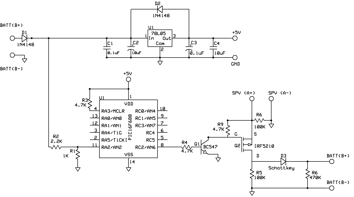
Here we are utilizing the 10bit Analog to digital converter module of PIC16F88 (18 pins) for doing this task.

Check points for Part 2.
1.If the visible alarm is ON, the sensing digital input of MCU will be high. If the alarm is OFF ,then it will be LOW .So according to this sensing I/O pin's status switch ON and OFF alarm. But the tricky thing over here is if user resets the Alarm , audio will be OFF, but still the sensing I/O pin status will be same as the visible alarm status. So here literally we need to sense a transition from LOW state to HIGH state and switch on the alarm.

The algorithm is having 3 functions mainly,
1.For sensing the battery voltage and switching the load- ADC_Function
2.For sensing the LOW to HIGH transition and switch on Audible Alarm-Alarm_Function
3.For Sensing the Reset button press and switch off Audible Alarm-Reset_Function


PROGRAM:-


/*********************************************************************************
*        Program for 10KW charge controller                                                         
*        Intelligent Load Management and Alarm monitoring System                                                                                           *
*        Author: Ravi M.D.                                                                                                                                                        *
*        R&D Engineer, Miconova Impex PVT LTD                                                                                                        *
*        Date 10/30/2012                                                                                                                                                                                         *
********************************************************************************/


#include <htc.h>
#define _XTAL_FREQ 8000000                   //Set frequency as 8MHz

#define Alarm PORTAbits.RA7                 //Assign I/O Pins
#define Signal PORTAbits.RA6
#define Reset PORTAbits.RA0 
#define Load PORTBbits.RB4
#define Lower_Voltage 0x015E               //Set the voltage ranges here. No need to change in program
#define Upper_Voltage 0x0101

//Internal Clock used at 8MHz

__CONFIG (FOSC_INTOSCIO & WDTE_OFF & PWRTE_OFF & MCLRE_ON & BOREN_OFF & LVP_OFF & CPD_OFF
                        & WRT_OFF & DEBUG_OFF &CCPMX_RB0 & CP_OFF);

__CONFIG (FCMEN_OFF & IESO_OFF);

unsigned int adc_value,adc_value1;adc_value2=0;      //Reading variables for adc higher and lower    registers
int i=0;                                                       //Variable for switch function
bit out_bit=0;                                                 //Bit used for Load ON and off


void Alarm_Function(void);                //function to rise alarm
void Reset_Function(void);                //function to reset alarm


void main(void)
{
 OSCCON=0b01110110;                                //Oscillator Setting  for 8MHz
 TRISA=0b01000011;                                //PORTA configuration
 ANSEL=0b00000010;                                //Only RA1 as analog input
 TRISB=0b00000000;                                //All pins are digital out


 ADCON1=0b10000000;                                //References are VDD and Vss and right justified
 ADCON0=0b10001000;                                //A/D clock as Fosc/2 and channel 1

 while(1)                                          //Check infinitely
 {
 switch (i)
            {

/*ADC_Reading for battery management*/

                case 0:                                                
                ADON=1;                                 //Start ADC Module
                __delay_us(100);                        //wait for acquisition time
                GO_nDONE=1;                             //Start conversion
                while(GO_nDONE);                        //Wait for conversion to be done
                ADON=0;                                 //Turn OFF ADC
        
                /*Reading the 10 bit ADC values*/
                
                adc_value1=ADRESL;                      //Read Lower 8bit registers
                adc_value2=(ADRESH<<8);                 //Read the higher 2 bits and shift it in to 8th and 9th position using shift function
                adc_value=adc_value2|adc_value1;        //OR both after reading to make a 10bit value
        
        
        /*Switch ON and OFF load according to the condition*/
        
                if(adc_value>=Lower_Voltage)            //Compare with lower voltage range
                out_bit=0;                              //If less than the (here negative voltage so thats why used greater than or equal) lover voltage level, switch OFF load
                
                if(adc_value<=Upper_Voltage)            //If greater than the (here negative voltage so that's why used less than or equal) upper voltage level, switch ON load
                out_bit=1; 
                
        Load=out_bit;                                    //Assign the decision to load.(Important, Its done here to resolve a fluctuation problem)
        break;


        /*Checking alarm conditions*/        
                
                case 1:
                ADON=0;                                  //taking precaution by switching OFF ADC and setting the same value as above to the load
                Load=out_bit;
                Alarm_Function();                        //check for alarm condition
                Reset_Function();                        //Check for reset condition
                
        break;
                
                }
 i++;                //Iteration variable to exit the switch case and repeat the process
        if(i>1)
        {
        i=0;
        }
 }
        

}


Sub Routines:-

1.Alarm_Function:-


#include <htc.h>

#define Alarm PORTAbits.RA7
#define Signal PORTAbits.RA6
#define Reset PORTAbits.RA0 

bit flag=0;                        //flag for identifying the signal transition from 0 to 1

void Alarm_Function(void)
{

if(!Signal)
        {
        flag=1;
        Alarm=0;
        }
        if(flag&&Signal)                //Check whether there is a signal change from 0 to 1 is happening
        {
        
                Alarm=1;
                flag=0;
        }
        
}     


2.Reset_Function:-


#include <htc.h>

#define Alarm PORTAbits.RA7
#define Signal PORTAbits.RA6
#define Reset PORTAbits.RA0 

void Reset_Function(void)
{

        if(!Reset)
        
        Alarm=0;

}


Friday, November 2, 2012

NorCal20 - Updates

Greetings,


Great news. We tested the NorCal20 receiver side today. The receiver IF was tested by feeding a RF Gen signal for the RCT of 8.998Mhz. A blasting crisp noise was heard.....PASSED.

The audio amplifier was also tested during the process.....PASSED

More updates awaiting.

10KW Solar Charge Controller - Tested and Parceled

Hello Everyone,


The above picture is the final stage of the 10KW Solar Charge Controller. This product has been sent to the customer for testing and reviews. We have already tested the unit in a Bangalore test facility (Our previous post has the history).